DPS Testing Report
Testing conducted by John Lamp at NSI, 12/4/2019- 12/6/2019
OBJECTIVES
A test series was designed and carried out to understand the functionality, features, and performance of the Metrix DPS configurable proximity probe vibration transmitter, MX2034. Metrix asserts the ability to replace competitive system components from Bently Nevada NSv, RAM, and 3000 Series. Tests were designed to evaluate the performance of the MX2034 with respect to three topics: linearity, crosstalk noise, and spike suppression, while also clarifying the functionality of the configuration software and settings.
LINEARITY TEST METHODS AND RESULTS
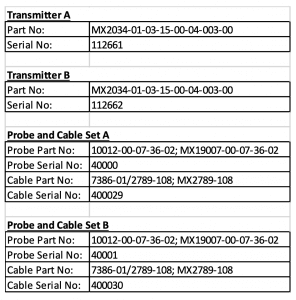
Two probe and cable sets, designed for one-to-one replacement of competitive 3000 series, NSv and RAM probes, were provided by Metrix and designated A or B, and two MX2034 transmitters were provided and designated A or B as well. Probe gap voltage curves were plotted into Excel files using a micrometer with a sample disk of AISI 4140 steel and the Metrix DPS Software Revision 1.35.510.1 with Database Version 1.14.
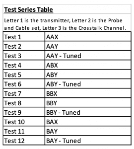
The crosstalk elimination channel selection was expected to affect the linearity, so an additional parameter was added to the test series to learn more about this effect. Channels designated as X or Y in the software were also labelled X or Y in the test series table. In the manual, Metrix recommends running a 2-Point tuning procedure after the crosstalk elimination channel is changed, so an additional parameter called “-Tuned” was added to the testing series table, but only for the Y crosstalk channel selection. A tuned X channel linearity test was not added to the test series, because each transmitter was already factory calibrated for the X crosstalk channel. The equipment designation and test series tables are below.
While the MX2034 has the ability to be custom calibrated for a specific probe and cable, the objective of this series of tests was to understand the linearity of the probe curve without calibrating, or “out-of-the-box” linearity. This method is intended to give greater insight about the expected performance of the MX2034 transmitter when paired with any probe and cable combination having the same part numbers used in this series of tests. To ensure consistency, the transmitters were returned to factory default settings using the software before each X-Channel test or before Tests 1, 4, 7, and 10.
The results of the X-Channel tests are shown below for each combination of transmitter and probe/cable set.
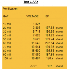
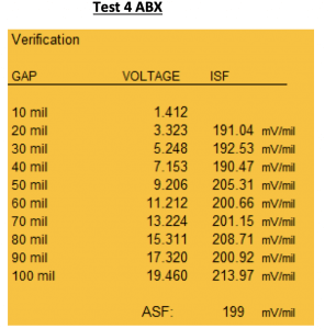
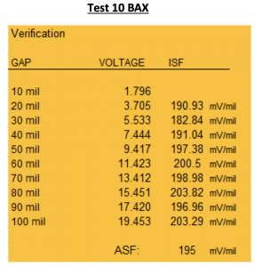
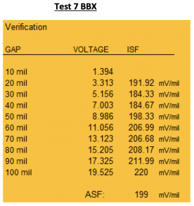
The “out of the box” X-Channel linearity performance results showed API compliant incremental scale factor (ISF) accuracy between 10 and 90 mils on the A transmitter for both probe and cables sets. The B transmitter was outside of API specifications for both probes, but well within the ISF accuracy specs defined by Bently Nevada, Inc. for 3300 XL NSv systems as quoted below.
7.87 V/mm (200 mV/mil) +12.5%/-20% including interchangeability error when measured in increments of 0.25 mm (10 mils) over the 1.5 mm (60 mil) linear range.
The X-Channel “out of the box” performance for both transmitters was linear within NSv ISF specs over the full measured range from 10 to 100 mils, which is greater than the 60 mil linear range requirement.
The X-Channel “out of the box” deviation from straight line (DSL) results, not shown in this report, were found to be within +/- 1.5 mils over the full 10 to 100 mils range. This is within the +/- 2.3 mils specified by Bently Nevada for NSv probe/cable/transducer systems. These results can be made available upon request.
Un-tuned Y-Channel results were found to be outside of linearity specs, and are not included in this report.
The two-step tuning procedure was performed after changing the configuration to the crosstalk elimination Y-Channel. This two-step process involved moving the probe to an open position (no metal near the probe tip) and pushing the software [Offset] button, then positioning the probe to 10 mils from the surface of the shaft sample and pushing the software [1 Volt] button. The Y-Channel results with the 2-Step tuning procedure completed are shown below.
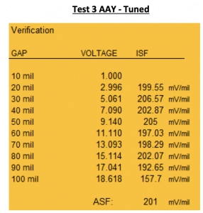
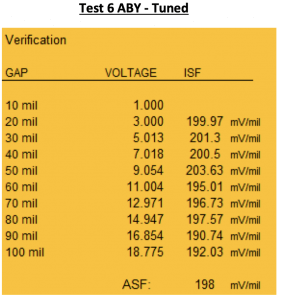
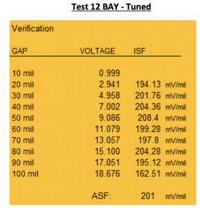
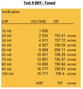
The Y-Channel linearity results, recorded after performing the 2-Step tuning process were found to be within API accuracy specification for ISF and DSL across all four combinations of transmitter and probe sets.
NOISE TEST METHODS AND RESULTS
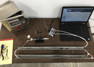
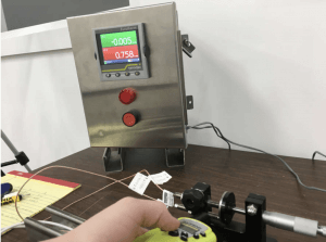
The 4-20mA signals, produced by the MX2034’s, were recorded to gain insight about the noise reduction performance of the crosstalk elimination feature. Transmitter B was left in the Y-Channel configuration with Probe and Cable A connected after the last linearity test ‘Test 12 BAY – Tuned.’ Transmitter A was returned to factory default settings and connected to Probe and Cable B. Then Transmitter A was checked to make sure the X-Channel configuration was selected. With the two transmitters set on different Cross-Talk Elimination Channels (X and Y), the probes were mounted and stabilized near the AISI 4140 target and gapped to between 6 and 13 Volts. The position of the probes was determined by moving the loose probe closer to the fixed probe until the output of both transmitters increased above zero. The loose probe was situated as close as possible, so that the output of both transmitters was still close to zero.

In the pictures above, the loose probe (Probe and Cable A) could be mounted approximately 0.25 to 0.375 inches from the tip of Probe and Cable B without influencing the output. The outputs of both channels settled at approximately -0.005 mils PK-PK in this setup. The test setup is admittedly delicate and difficult to reproduce, given the angle of the loose probe, but the results should be useful for evaluating the behavior of noise in the systems rather than physical vibration. In addition to the relative proximity of the probe tips, the cables were run through steel U-channel and wound several times to create ‘worst-case’ signal interference situation. An overhead picture of the test setup is shown below.
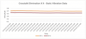
After the data had stabilized, the test setup was left alone to record static vibration data with no substantial physical movement for a couple hours. The purpose of the test was to record noise in the system, defined as anything other than physical vibration that might cause the 4-20mA analog vibration amplitude output signal to read above zero. With the transmitters set to different Crosstalk elimination channels (X and Y), the output was expected to be close to zero. A plot of the recorded data is shown below.
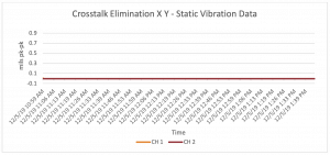
The analog vibration amplitude output was recorded at between -0.005 and -0.006 for the duration of the test. This value is assumed to be essentially zero with a small negative offset likely due to error in the value of the measurement resistor or other static circuit factors.
Transmitter A was then returned to default factory settings while the probes were left in the same position. The Crosstalk channel was confirmed to be set to X, so that both transmitters were set to the same channel (X X). The analog 4-20mA signal data was recorded again for some time in the same way as the previous test. Data from this test is shown below.
The noise recorded for the X and Y configuration was very low and stable around -0.005 mils pk-pk (essentially zero), while the X X configuration generated anywhere between 0.5 and 1 mil pk-pk of noise.
With both transmitters set to the X-Channel, the position of the two probes did have a noticeable effect on the level of noise in the 4-20mA signal. As the loose probed was moved further from the fixed probe, the level of noise seemed to decrease, although no additional testing was done to quantify the extent of this effect. It’s noted that the results of this testing may be difficult to duplicate. Further, it was observed that if the two probes tips were touching or located within approximately 0.25 inches, the noise was elevated for both X X and X Y configurations. Again, no additional testing was done within this close distance to compare the level of noise between X X and X Y configurations.
With the cables wound through the U-channel, there was some concern that the signals would interfere through the cables even if the probe tips were not located close together. This effect was not observed in either X X or X Y configuration. In both X X and X Y configurations, the analog vibration amplitude output would stabilize near zero if the probes tips were mounted and secured far enough away from each other. Adjusting and shaking the cables likewise did not seem to have an effect on the output. These observations about the cables were not tested or recorded.
SPIKE TEST METHODS AND RESULTS
Three tests were conducted using a walkie-talkie to generate electromagnetic interference and evaluate the performance of the spike suppression feature in the MX2034’s. By pointing a walkie-talkie antenna at the probes and pressing the talk button, some noise was observed in the signals. It was difficult to predict how much noise would occur or which position and radio channel had the greatest effect. After several attempts, a position was found that seemed to consistently generate high noise on both probes when the talk button was pushed. This position is shown below for Spike Test 1.
Three tests were conducted to record the effect of enabling and disabling the spike suppression feature. Prior to the tests, transmitter A was set to the Y Crosstalk channel and a two-point tuning procedure was performed. Transmitter B was returned to factory default and left in the X Crosstalk channel. In the first two tests, only one of the transmitters had spike suppression enabled and the other did not. In the third test, both transmitters had spike suppression enabled. These tests were performed while holding the walkie-talkie and pressing the talk button repeatedly. Data from these three tests is shown below.
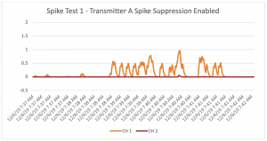

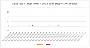
In both of the first two spike tests, the transmitter with spike suppression enabled had a reduced vibration noise response to the walkie-talkie interference. As shown most clearly in the third test, the spike suppression feature did not fully eliminate all the vibration noise, but considerably reduced the noise output caused by walkie-talkie interference for both transmitters.
ANALYSIS AND FINDINGS
LINEARITY:
The Metrix MX3000 series probes and cables with MX2034 transmitter were not found to meet API compliant performance specs consistently out-of-the-box, but were found to meet the performance requirements specified by Bently Nevada for 3300 XL NSv probes for ISF and DSL accuracy.
Changing the configuration of the transmitter from the X-Channel to the Y-Channel required the proximity system to be tuned using the two-step tuning process. After tuning, the transmitters were able to achieve API compliant linearity. NSI contacted Metrix and explained that customers will likely request factory configured Y-Channel transmitters that do not require a 2-step tuning process. Metrix has agreed to make this option available, allowing air compressor manufacturers and end-users to avoid the tuning process and still make use of the cross-talk elimination feature. However, it is established that anytime the Crosstalk Channel is changed from the factory configured setting, the linearity must also be confirmed by either performing a 2-Step Tuning process or a custom calibration.
CROSSTALK ELIMINATION:
The crosstalk elimination feature was tested and found to be effective at reducing and/or eliminating vibration noise in the analog 4-20mA output caused by mounting two probes close together.
SPIKE SUPPRESSION:
The spike suppression feature was found to be effective at reducing noise in the analog 4-20mA output caused by nearby electromagnetic interference spikes from a walkie-talkie. This result should be considered and applied with caution. Not all types of electromagnetic interference could be tested and the troublesome signal behavior known as ‘electrical spikes’ can be caused by a wide variety external factors. The MX2034 is likely not immune to all types of electrical spikes, but may be able to prevent the shutdown of a machine by reducing the effect of some sources of electrical spikes on the 4-20mA output.
COMMENTS:
Since learning about the obsolescence of Bently Nevada’s older probes and cables, Metrix has devoted notable design and development effort to making the MX2034 databases robust enough to ensure good linearity out-of-the-box for both X and Y configurations when paired with MX3000 and BN3000 series probes. Based on these tests, Metrix meets the specs published by the generally accepted industry standard offering from Bently Nevada for NSv probes (as a comparison reference point), but does not yet meet API specifications consistently out-of-the-box for ‘narrow’ or ‘tight’ probe installation applications with competitive probes and cables. The custom calibration functionality of MX2034 transmitters was not included in this test series; however, it may be useful for customers who need to achieve API linearity, even in tight or narrow probe installation applications. Given the continued investment in testing and the time Metrix has devoted to improving the software, the linearity performance of the MX2034 will likely continue to improve.
The crosstalk and spike suppression features incrementally improve the functionality of this technology by reducing the number of mechanisms for false-trips. These two features should be tested more fully to understand their limitations, but the initial impression is that they can be very effective in avoiding some common causes of unnecessary machine shut downs.
LIMITATIONS:
1. Metrix regularly updates the firmware, software, and database files used by this equipment.
These updates are usually intended to improve performance of the equipment and may be expected to affect the results of this test series.
2. For new applications, Metrix recommends the MX8030 probes series for best linearity and consistency out-of-the-box, as well as interchangeability with competitive systems. These tests were conducted using MX19007 probes for a specific BN3000 replacement application.
3. The author of this report is an agent of Metrix; however, effort has been taken to consider these results through an objective empirical viewpoint.