Blog
June 19, 2026 | Company NewsProduct News

The industrial sensing and tank gauging landscape continues to evolve as leading technology providers consolidate to better serve regulated industries like oil & gas, petrochemical, and bulk liquid storage.
Recently, Cognesense brought together two highly respected brands in this space, L&J Technologies and Varec, under a unified platform focused on measurement, monitoring, and industrial safety.
Both companies have long histories in tank gauging, inventory management, and liquid measurement systems used across terminals, pipelines, refineries, and storage facilities.
A Unified Platform Approach
By combining these legacy technologies under Cognesense, the goal is to create a more integrated ecosystem across:
- Tank gauging and level measurement
- Inventory and terminal management software
- Environmental and operational monitoring systems
- Safety and compliance-driven industrial applications
For operators, this consolidation is designed to improve long-term product alignment while maintaining continuity of existing systems.
What This Means for Oil & Gas Operators
For end users in the oil and gas sector, this transition does not remove or replace existing systems. Instead, it reinforces continued support for installed technologies while aligning future development under a single strategic platform.
Operators in:
- Pipeline infrastructure
- Storage terminals
- Refineries
- Bulk liquid handling facilities
can expect continued availability of L&J and Varec technologies with enhanced integration over time.
NSI’s Role: Continued Local Expertise and Distribution
Neal Systems is proud to announce that we are now an official authorized distributor for both L&J Technologies and Varec under the Cognesense platform.
This allows NSI to provide:
- Direct access to both product lines and 25+ other top-tier lines
- Application engineering support for system selection and design
- Assistance with upgrades, replacements, and legacy system integration
- Local expertise across the Mid-Atlantic
As the industry continues to consolidate, having a knowledgeable partner becomes increasingly important. NSI remains committed to helping customers navigate these changes while ensuring reliable, compliant, and efficient operations.
If you are currently using L&J or Varec systems or planning a new project our team is available to support your application needs.
June 3, 2026 | Product News
See below for a list of helpful resources for Geo SCADA users. The links include YouTube videos- as well as product pages, data sheets, and download links.
Geo SCADA Expert
Geo SCADA – Downloads index (current versions & ISOs):
https://community.se.com/t5/Geo-SCADA-Knowledge-Base/Geo-SCADA-ExpertDownloads/ba-p/279115
Geo SCADA – Product page:
https://www.se.com/us/en/product-range/61264-ecostruxure-geo-scada-expert/
Geo SCADA – brochure:
https://www.se.com/nz/en/download/document/Geo_SCADA_Brochure_Ltr/
Geo SCADA – 2025 Release Notes download:
https://www.se.com/us/en/download/document/Geo_SCADA_Expert_2025_Release/
Geo SCADA – Resource Center (Knowledge Base home): https://community.se.com/t5/GeoSCADA-Knowledge-Base/Resource-Center-Home/ba-p/279133
Geo SCADA – Operating System Support – Geo SCADA 2025:
https://community.se.com/t5/Geo-SCADA-Knowledge-Base/Geo-SCADA-2025-OperatingSystem-Support/ba-p/517788
Geo SCADA – Upgrade Strategy – 2025: https://community.se.com/t5/Geo-SCADAKnowledge-Base/Geo-SCADA-2025-Upgrade-Strategy/ba-p/517790
Geo SCADA – Upgrade Notes – 2025: https://community.se.com/t5/Geo-SCADAKnowledge-Base/Geo-SCADA-2025-Upgrade-Notes/ba-p/517789
Geo SCADA – Online Help (all versions): https://tprojects.schneiderelectric.com/GeoSCADAHelp/
Geo SCADA – Technical Guides (incl. Procurement Spec):
https://community.se.com/t5/Geo-SCADA-Knowledge-Base/Technical-Guides/bap/278414
Geo SCADA – Mobile app update FAQ, Changes to Geo SCADA Mobile 2025: https://www.se.com/ca/en/faqs/FAQ000278099/
SCADAPack x70 / 47xi
SCADAPack – SCADAPack 470 & 474 Datasheet (Letter):
https://www.se.com/us/en/download/document/SCADAPack_470_474_RTUs_DS_Ltr/
SCADAPack – SCADAPack 470i & 474i Datasheet (Letter):
https://www.se.com/us/en/download/document/SCADAPack_470i_474i_DS_Ltr/
SCADAPack – SCADAPack x70 Smart RTUs consolidated datasheet:
https://www.se.com/us/en/download/document/SCADAPack_x70_Smart_RTUs_Ltr/
SCADAPack – RemoteConnect download:
https://www.se.com/us/en/download/document/RemoteConnect/
SCADAPack – RemoteConnect – How to download FAQ:
https://www.se.com/us/en/faqs/FAQ000262603/
SCADAPack – Download Links Hub for Remote Operations software (FAQ):
https://www.se.com/us/en/faqs/FAQ000272686/
SCADAPack – EcoStruxure RTU Operation Expert (EROE) Studio – software download: https://www.se.com/us/en/download/document/EROE_Software/
SCADAPack – RemoteConnect Documentation Installer:
https://www.se.com/us/en/download/document/RemoteConnect_Documentation/
SCADAPack – Lift Station Libraries
https://www.se.com/in/en/download/document/Lift_Station_Libraries/
SCADAPack – Documentation general
https://www.se.com/us/en/product-range/35344468-scadapack-47x-47xi/?parentsubcategory-id=6040&filter=business-1-industrial-automation-and-control#documents
Realflo
Realflo – Realflo software download (latest):
https://www.se.com/us/en/download/document/Realflo_Flow_Computer/
Realflo – Realflo datasheet, TBULM08002-71-v26-Letter:
https://www.se.com/us/en/download/document/Realflo_Flow_Computer_DS_Ltr/
Trio Data Radios
Trio – Trio Data Radio Brochure (Letter):
https://www.se.com/us/en/download/document/Trio_Data_Radio_Brochure_Ltr/
Trio – Trio J Series datasheet
https://download.schneiderelectric.com/files?p_Doc_Ref=Trio_JSeries_Unlicense_DS_Ltr&p_enDocType=Brochure&p_Fil
e_Name=SE-DataSheets-TrioJR-Letter-TBU-v19.pdf
Trio – Trio Q – QB datasheet:
https://www.se.com/us/en/download/document/TBULM08003-40/
Trio – Trio Q – QP datasheet:
https://www.se.com/us/en/download/document/TBULM08003-44/
Trio – Trio Q – QH datasheet:
https://www.se.com/us/en/download/document/TBULM08003-46/
Trio – Trio Q – QR datasheet:
https://www.se.com/us/en/download/document/TBULM08003-42/
Trio – Radio Path Study Request Form (Scroll through page to locate download file)
https://www.se.com/us/en/product-range/61420-trio-licensefree-radios/?parentsubcategory-id=6010&filter=business-1-industrial-automation-and-control#documents
YouTube Playlists
YouTube – Geo SCADA Expert – official playlist:
https://www.youtube.com/playlist?list=PLa7UGrWOTyjnPpCJxnTZkdBM_6D70qoKl
YouTube – SCADAPack 47xi – official playlist:
https://www.youtube.com/playlist?list=PLa7UGrWOTyjlQDe7aUVhvUHR3OOLV3Q_i
YouTube – RemoteConnect – An Introduction (5 videos)
https://www.youtube.com/playlist?list=PLa7UGrWOTyjkqNKdn25f6P2wE_DMNrZuj
YouTube – RemoteConnect Getting Started (30+ videos):
https://www.youtube.com/playlist?list=PLa7UGrWOTyjlyww9RcENfi8u9i8SKPZ0c
YouTube – RemoteConnect – DNP3 Basics:
https://www.youtube.com/playlist?list=PLa7UGrWOTyjkCEOPlYRwAOB7GGFoLy5WS
YouTube – Realflo – Gas Flow Computer Series:
https://www.youtube.com/playlist?app=desktop&list=PLa7UGrWOTyjkB9WW4to5XBv4A
eYZIoQEP
YouTube – SCADA in Sixty – official playlist:
https://www.youtube.com/playlist?list=PLa7UGrWOTyjnKdTZFdtKEt_QSI4YBRszw
YouTube – Trio Radios – official playlist:
https://www.youtube.com/playlist?list=PLa7UGrWOTyjlpwf0J9GEFDovU9vFKYM6l
YouTube – Schneider Electric Modicon NTS Remote I/O as SCADAPack Remote I/O –
https://www.youtube.com/playlist?list=PLa7UGrWOTyjmszQcCLS7buPEPdfh0cuL3
List of all Remote Operations videos, includes others not in the above playlists:
https://community.se.com/t5/Remote-Operations-Blog/YouTube-Video-List-andLinks/ba-p/398632
April 28, 2026 | Company NewsProduct News
We’re excited to share that Neal Systems (NSI) is now the official representative for KELLER Pressure in Maryland and Virginia.
Over the past year, we’ve supported KELLER across the Northeast helping customers implement reliable pressure and level measurement solutions in real-world applications. Expanding into MD and VA allows us to bring that same level of service, responsiveness, and technical support to a broader region.
Why KELLER?
KELLER has consistently impressed us – not just on paper, but in the field.
Their submersible level transmitters, in particular, stand out for their:
- Reliability in demanding environments
- Accuracy you can count on
- Practical features, like re-ranging via RS485
Add in U.S.-based manufacturing in Virginia and fast turnaround times (often under a week), and it’s a solution that’s built to perform and keep your projects moving.
Request a quote here.
What This Means for You
If you’re operating in Maryland or Virginia, you now have direct access to:
- Local support
- Application guidance from engineers who understand your challenges
- A partner who stays involved beyond the initial install
Meet Your Local Resource
Supporting this region is Shaun Baines, Territory Manager for Maryland, D.C., and Virginia.

Shaun brings a unique background, including 20 years in aviation engineering with the U.S. Coast Guard, along with an MBA from Auburn University. He now leads NSI’s efforts in the region, working directly with customers to solve application challenges and deliver reliable solutions.
When he’s not working with customers, you’ll likely find him on his 40-acre farm in Louisa, VA – usually with a few projects (and animals) to keep him busy.
Visit his bio page here to contact him directly.
About Neal Systems (NSI)
We help customers solve real-world challenges across pressure & flow, wireless, data acquisition, RTUs, SCADA, and more.
Our goal is simple: be a true partner. That means responsive support, practical engineering expertise, and solutions that work in the field.
Visit our service and solutions page for our offerings or contact us here.
February 10, 2026 | Product News
Weighing and feeding equipment is critical in the cement industry to provide accuracy, process stability, product quality, and energy efficiency. The cement industry requires robust, specialized conveying and feeding equipment to handle a variety of bulk materials, including abrasive materials ranging from limestone to fine powders. The equipment must provide continuous and precise flow of materials and operate in extremely harsh and strenuous operating conditions.
Cement manufacturers rely on rugged and durable conveying and feeding equipment in each step of the process. They must accurately track and measure inbound raw materials (e.g., gypsum, clinker, silica and limestone) and closely monitor in-process material consumption. In addition, precise ingredient blending and accurate final-product dispatch is also critical to product quality and operational efficiency.
Conveying Equipment
Robust conveying equipment is essential, it is used to transport materials between different stages of the production process, and the distances can be far. Belt conveyors are the most common and versatile conveyors used for long-distance and high-capacity transport and continuous and precise feeding of bulk materials such as limestone, clay and clinker. These heavy-duty conveyors can be run horizontally or on an incline and utilize robust belts and components that are heat-resistant, durable and designed to withstand harsh environments. These Conveyors also often incorporate Belt Scales to continuously measure the mass flow of the bulk materials and these must also be extremely durable while able to consistently and accurately provide critical process data.
Bucket Elevators are used for vertical transport to lift materials like raw meal, clinker and finished cement from a lower point in the production process to a higher one. They are compact and have a tall lifting range to move material, such as feeding material into a grinding mill or storage silo.
Pneumatic Conveying Systems use air pressure (or vacuum) to move powdered materials (like finished cement) through sealed pipelines over long distances. They offer excellent material containment, preventing dust emissions and their pipelines can be routed around obstructions but these systems do require additional equipment including blowers and air filters.
For short-to-medium distances, Screw Conveyors can be used to transport fine, powder-like materials, such as fly ash, cement, and dust. They have a rotating screw inside a trough or tube and are ideal for controlled volumetric feeding and dust containment.
Feeding Equipment
Feeding equipment is required to extract material from storage (hoppers or silos) and to deliver it continuously and uniformly into process machines such as crushers, mills, or kilns at a precise, controlled rate.
Vibratory Loss-in-Weight Feeders are suitable for feeding bulk materials, such as coarse limestone, before they enter a crusher. Vibration is used to move and regulate the flow of the material, including irregular shapes, larger particles, pellets, and powders.
Table Feeders are used to extract and feed smaller, granular or powdery non-sticky materials from silos or hoppers with an adjustable flow rate, often for blending purposes.
More robust heavy-duty apron feeders that use metal plates (aprons) linked by chains serve to extract and feed very large, heavy and highly abrasive raw materials, such as run-of-mine ore from hoppers, especially for primary crushing applications.
Rotary Feeders can be used control the discharge rate of fine, powdered material from storage and act as an airlock in pneumatic conveying applications and to minimize cold air leakage into high-temperature systems like the raw mill inlet.
Weigh Belt Feeders
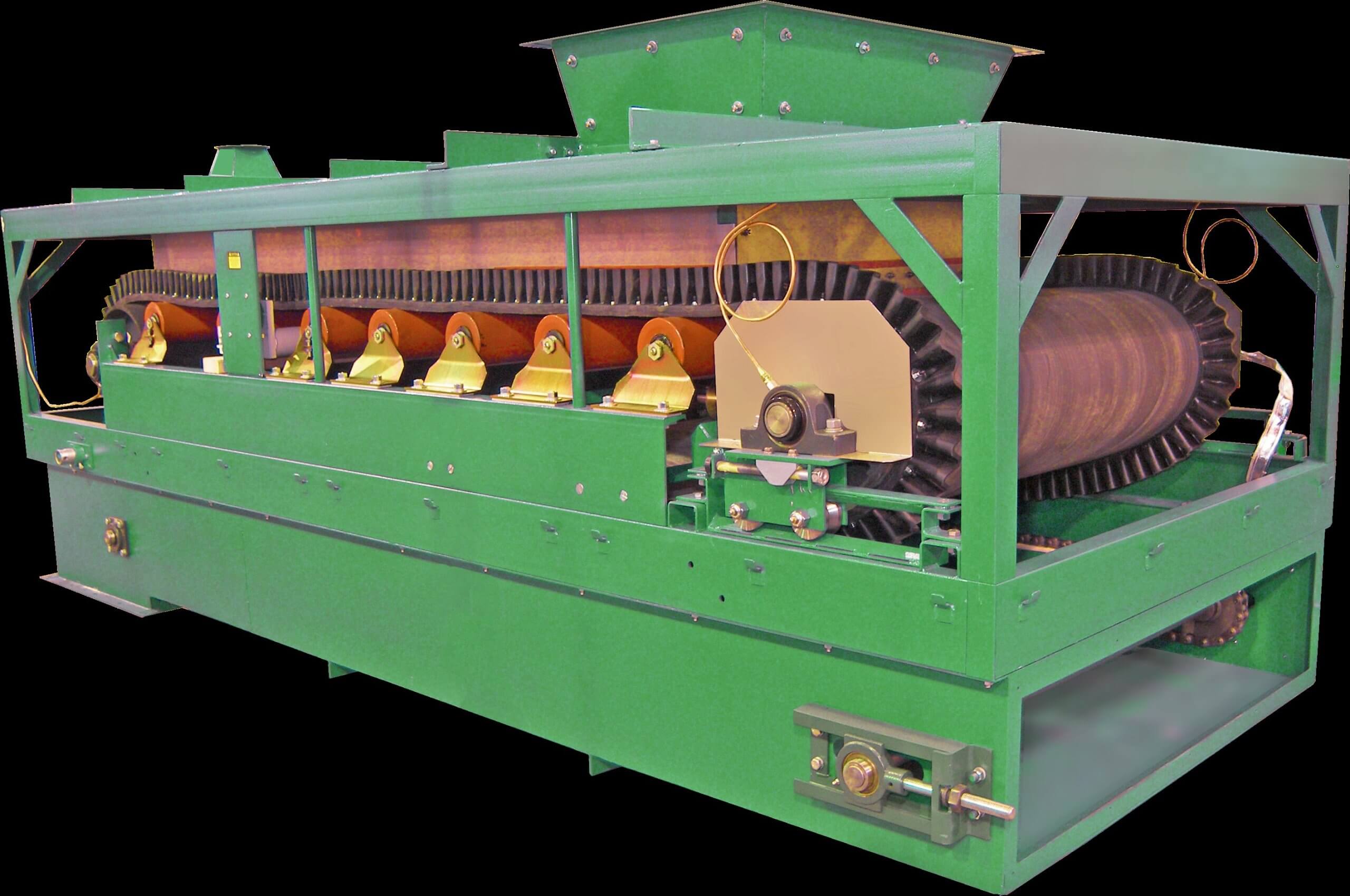
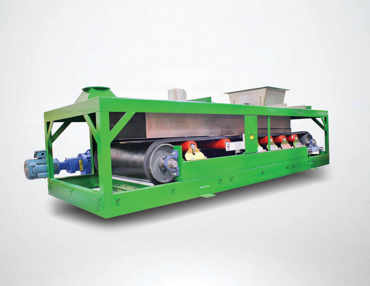
Weigh Belt Feeders (or Weigh Feeders) are ideal for a range of controlled feeding and accurate material proportioning applications. These are short, self-contained, belt conveyors that incorporate an integral belt scale and can be used to continuously monitor and control the material mass flow rate before it enters key processes (raw mill or kiln). These are critical for quality control and blend optimization. They provide high precision, are excellent for a wide range of feed rates and suitable for blended cement production.
Originally developed in the 1970s for the cement industry, Thayer Scale’s Model MD & MDL feeders are extremely rugged weigh belt feeders commonly used across many heavy industrial applications. These Weigh Belt Feeders are proven to withstand extreme environmental conditions, including abrasive dusts, corrosive fumes, wide temperature fluctuations and vibrations – without any detrimental effects to performance or accuracy. With the Model MD being able to handle flow rates between 2 – 400 STPH and the MDL being specifically designed for the lower end of that range, both styles of feeder offer a range of rugged weigh belt options ideally suited for harsh industrial environments.
The Model MD and MDL are suitable for heavy, compacted, high bulk density materials of all particle sizes. They are the ideal feeders for medium to high feed rates for both general and heavy industrial applications.
Built to Survive
Recently, Neal Systems sold a replacement Weigh Belt Feeder to replace a unit originally installed in 2008 in a harsh outdoor cement production environment. Being “Built to Survive” this equipment had been running well for nearly twenty years, providing accurate rate measurement. After many years of reliable service, the frame of the feeder was beginning to succumb to corrosion under the harsh operating conditions. The replacement unit was upgraded to a full stainless-steel frame construction, which will result in an even longer service life
The Weigh Belt Feeder, a Model MD-24-TM, is used to meter iron ore into the production process. Iron ore is added to cement to enhance its strength and accelerate the hydration process. As a fluxing agent, iron ore helps chemical reactions with calcium and aluminum during high-temperature processing, forming compounds like tricalcium aluminoferrite, which contributes to the hardness and strength of the cement.
This manufacturer uses several other Weigh Belt Feeders and Conveyor Belt Scales in their cement product process to handle materials like limestone, gypsum, clinker, petroleum, coke, slag, fly ash, all used to create a variety of construction materials.
In addition to the cement industry weighing and feeding equipment is used throughout a wide range of industries and bulk material handling applications and it is essential to have the correct equipment in place to ensure the accurate and precise flow control of material at every stage of your process.
To learn more about how Neal Systems and Thayer Scale can help with your Weighing and Feeding needs, please contact us here.
February 3, 2026 | Company News
|
|
We’re excited to officially share that Neal Systems has acquired New England Temperature Solutions (NETS), owned by our longtime friend, Dominick Deluca.
This acquisition was finalized on January 1, 2026, and represents and exciting new chapter for both companies and our customers. Click here to see our initial announcement.
|
|
|
|
|
For years, NETS has built a strong reputation for technical knowledge, customer trust, and having fun along the way. That approach aligns closely with how we operate at NSI.
Dominick recently sat down with Dave Neal (Owner) and Shane Filer (President) to discuss why this partnership makes sense, what it means for customers, and where we’re headed next. Watch the conversation — there’s even some humor in the second half.
|
|
|
|
|
|
|
We combine engineering expertise, best-in-class products, and practical solutions to help our customers meet their process and control needs. Our team provides support every step of the way:
⮞ Application guidance & instrumentation selection
⮞ Calibration & preventative maintenance
⮞ Installation & commissioning
⮞ Engineering services
|
|
|
|
|
We’d like to introduce some members of our team and welcome a new engineer who has joined us from NETS.
These are the folks who provide application guidance, technical support, and solutions that our customers rely on everyday.
|
|
|
Dexter Vilar
With 27 years in industrial controls and a BSEE from Penn State, Dexter specializes in Eurotherm controllers and process heating systems. He also teaches training classes and enjoys tackling design challenges.
|
|
|
|
|
|
|
|
|
|
|
|
|
|
|
|
|
|
Hugh Davison
Hugh holds a B.S. in Systems Engineering from the U.S. Naval Academy. He specializes in temperature control, SCADA, and industrial networking. Outside of work, he enjoys spending time with his family.
|
|
|
|
|
|
|
|
|
|
|
|
|
|
|
|
|
|
Joe McCracken
Joe has over 20 years of experience, including time at Eurotherm in England, and is an ISO17025-certified aerospace temperature and data specialist. He ensures precise installation, calibration, and field support while solving complex technical challenges.
|
|
|
|
|
|
|
|
|
|
|
|
|
|
|
|
|
|
Andy Bowser
Andy joined Neal Systems from NETS, where he specialized in temperature process control, heaters, and data acquisition. He holds degrees in mechanical engineering and mechatronics from Northeastern University and brings hands-on curiosity to every project.
|
|
|
|
|
|
|
|
|
|
|
|
|
|
|
|
|
|
Stephen Arnold
Stephen has 35+ years of industrial automation experience and leads high-precision temperature, process, and safety projects at Neal Systems. Outside of work, he enjoys biking and spending time outdoors, a passion he’s had since growing up in England.
|
|
|
|
|
|
|
|
|
|
|
|
|
|
|
|
See more faces behind NSI’s customer care, applications, solutions, service, and leadership teams on our Team page.
Curious how we work? Watch The NSI Story to get an inside look at our team, our approach, and what drives the way we deliver solutions for our customers.
|
|
|
|
|
|
|
|
|


