How to Choose the Right Seismic Sensor for Your Application
April 4, 2024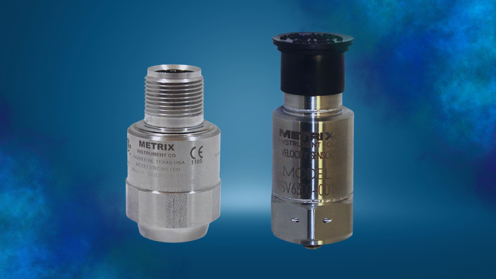
Choosing the right seismic sensor for your application – accelerometer or velocity sensor
In this blog post, we are discussing seismic sensors, which typically means we’re talking about machines with rolling element bearings. For machines with fluid film bearings, we typically use proximity sensors that can be augmented with casing mounted seismic sensors. At Metrix, we differentiate seismic sensors and seismic transmitters by the output needed by the monitoring or protection system. If the customer needs a 4-20 mA output, then a seismic transmitter will be used. Here we will be focused on seismic sensors, which provide a voltage output to a monitoring system. The seismic sensor outputs are in terms of acceleration or velocity, depending upon the machinery application needed. If the machine speed is 60 Hz or less, a velocity sensor is typically used. A velocity sensor is used because the bearing related, and rotor related, malfunction frequencies have the best signal to noise ratio. If the machine speed is greater than 60 Hz, then an accelerometer is typically used because it provides a better signal to noise ratio.
A seismic vibration sensor is inertially referenced, meaning that, if the sensor is not shaking, then the sensor will not produce a vibration output. Another way to say this is if you shake the seismic sensor on the earth or on the moon with the same force and frequency, you’ll get the same output. Seismic sensors are used to measure the motion of a casing of a rotating or reciprocating machine. The casing motion is usually indicative of the condition of the machine.
Seismic Sensors: General Considerations
Velocity Sensors
There are three basic types of velocity sensors, electromechanical, piezoelectric, and MEMS. An electromechanical velocity sensor uses a moving coil in the presence of a magnetic field to generate a voltage proportional to velocity, or the movement of the casing to which the velocity sensor is connected to. The piezoelectric velocity sensor takes advantage of the piezoelectric crystal inside, similar to an accelerometer, along with an integration and amplification circuit that converts the acceleration signal into a velocity signal. The MEMS (Micro-Electrical Mechanical Systems) velocity sensor takes advantage of the change in capacitance between small metal plates measured at the micro-millimeter scale. All these sensors have their advantages and disadvantages.
Even though the electromechanical velocity sensor has moving parts, its chief advantage over other velocity sensors is its ability to handle very high temperatures up to 375° C (707° F) without having to worry about melting integrated circuits. You see these types of sensors used on machines with relatively light casings and heavy rotors in high temperature environments, typically gas turbines.
The piezoelectrical velocity sensor is frequently used because of its solid-state design and its wide frequency range, typically from 2 Hz to 2,000 Hz. The piezoelectric velocity sensor is usually limited to 120° C (248° F). This velocity sensor does a great job at monitoring rolling element bearing machines that operate at 60 Hz or less. They’re also useful in measuring casing vibration on fluid film bearing machines when high temperatures are not encountered.
A MEMS velocity sensor is usually used for balance of plant equipment where a triaxial velocity sensor may be useful. The MEMS sensor can have a wide frequency range from 10 Hz to 5,000 Hz and is usually limited to 120° C (248° F). It should be understood that vibration is a ratio of forces to stiffnesses. A triaxial velocity sensor placed on top of the machine will not have the same X, Y, and Z axis readings as a triaxial velocity sensor placed horizontally on the machine due to the change in mechanical stiffness between the horizontal and vertical directions. For this reason, a single axis MEMS sensor can often provide more value when mounted properly on the machine.
Accelerometer Sensors
An accelerometer is a transducer that converts mechanical acceleration into an electronic signal. This is usually measured with a piezoelectric or MEMS device. The seismic sensors made from a piezoelectric material which produces a charge output proportional to acceleration (pC/g). When housed together with an electronic charge amplifier and charge-to-voltage converter (mV/g), it is referred to as an “internally amplified” accelerometer. If, due to temperature, only the sensor is machine mounted, the remote electronics are referred to as a “charge amplifier” (although it usually also contains a charge-to-voltage convertor). The MEMS accelerometer measures the acceleration by measuring the capacitance change between two surfaces. The output of the MEMS accelerometer is amplified and scaled to provide the same output as standard piezoelectric accelerometers.
Accelerometer sensitivity is a specification of the ratio of the accelerometer’s mechanical input to electrical output typically specified at a 100-Hz reference frequency or, as in the case of accelerometer frequency response, as a function of a range of frequencies.
Accelerometer frequency response is a specification of the accelerometer sensitivity as a function of frequency. Most accelerometers use the industry standard scale factor of 100mV/g or 10.2mV/m/s2. Accelerometers can have scale factors that range from 10 to 500 mV/g depending upon the sensitivity required. As the sensitivity increases, the frequency range increases. Typical frequency ranges for industry standard accelerometers are usually from 2Hz to 10kHz. Oftentimes the accuracy of the sensor is better at lower frequencies, like 2Hz to 5kHz, the accuracy may be +/- 5%. Whereas, from 2Hz to 10 kHz, the accuracy may be +/- 10%.
Summary
The above general guidelines should be helpful in determining whether to use a velocity sensor or accelerometer. One needs to consider the vibration frequencies of interest, the signal to noise ratio of a given sensor to the expected output, the environmental conditions, and mounting considerations. To learn more about this topic, also read our companion whitepaper titled “Accelerometers Versus Velocity Sensors – What’s the Difference?”
All the advancements in sensors have been focused on precision, building in measurements on small scales that can give operators a better understanding of the trends that are taking place in their operations. Metrix sensors have been improved upon over the years to provide insight to identify how machinery vibration is changing over time, so you can schedule repairs and maintenance long before you must shut the machine down. For more information, please contact Neal Systems.